


Equipment Required for the Installation of the Cintec™ Anchoring System
| The following pressure pots are available from: | |
|---|---|
| Graingers USA | 1-800-323-0620/ Refer to your local telephone directory |
| Canada | 1-800-633-8487 |
| Puerto Rico/Eastern Caribbean | 1-800-842-9107 |
| Bahamas/Jamaica | 1-800-897-4789 |
| Mexico | 95-210-717-0050 |
| Central/South America | 1-305-591-25 |
Speedair 2 1/2 Gal (9L) Part No. 6Z899. Max Working Pressure 50 P.S.I.
Speedair 10 Gal (37L) Part No. 4F966. Max Working Pressure 110 P.S.I.
1 1/4 NPT Plug – Part No. 5P541
1 1/4 NPT Male Plug Plus (for airline quick coupler) – Part No. 2X169
3/8 NPF 1/2” Hose Barb – Part No. 4A490
To complete the unit you will need:
- 12 Ft (4m) of reinforced (braided) tubing. 1/2” quarter turn ball valve. An 1/2” hose adaptor or threaded attachment needs to be screwed into the valve to enable plastic mastic nozzles to be pushed or threaded onto the front of the valve. This assembly will then serve as the grout delivery hose and control valve.
- 7 to 10 c.f.m compressor (minimum)
- Mixing paddle or whisk with a 6” cage.
- Electric drill for mixing (560 r.p.m. e.g Bosch GSB90-2E.)
- Two large mixing buckets (18 litre/5 US Gal min.)
- Measuring jug in litre increments.
- A large flour sieve (small mesh)
- Power generator or 110v transformer
- An adequate supply of mastic nozzles to suit control valve on delivery hose.
- Safety goggles and gloves
Similar equipment can also be purchased from Home Depot, Builders Warehouse, or a paint equipment supplier.
Should you have difficulty in locating equipment, please phone Cintec™ International Ltd.
All equipment must be kept in a clean condition. Do not use oil or releasing sprays inside the pressure pot as this may contaminate the grout.
Safety goggles and gloves must be worn at all times when mixing and injecting grout.
Drilling
Carefully set out the anchor position using a wax crayon or chalk, as per specifications, or as directed by the structural engineer or supervisor.
Select the drilling method specified:
Wet diamond -dry diamond – rotary percussion – or other
- Drill the hole to the required depth of the anchor and the embedment depth required.
- Remove all cores from the bore hole and check the depth.
- Flush out all bore holes with water or compressed air to remove all dust and debris.
- Wash off all stains immediately.
- Drilling blind into substrates requires special care. Substrates must be checked to ensure that it is as indicated. If not notify the engineer or supervisor. A particular problem is ending the drill hole in a void larger than the anchors expansion capabilities. Careful checks must be made if this is suspected and the engineer or supervisor informed.
- Bore holes in loose material MUST BE SLEEVED IMMEDIATELY AFTER DRILLlNG to facilitate anchor insertion and prevent the need for re-drilling.
Anchor Insertion
- Carefully unpack the anchor and check there has been no damage to the fabric sock during transit. All damages must be reported to Cintec™ International Ltd.
- Small tears or rips in the sock can be repaired using a needle and strong cotton or a hot melt glue stick.
- Do not shorten the length of the sock on the anchor.
- At this stage the anchor must be handled with extreme care. And it should not be unwrapped until required.
- Some long anchors require sleeves to protect the anchor during insertion, where ever possible use sleeves
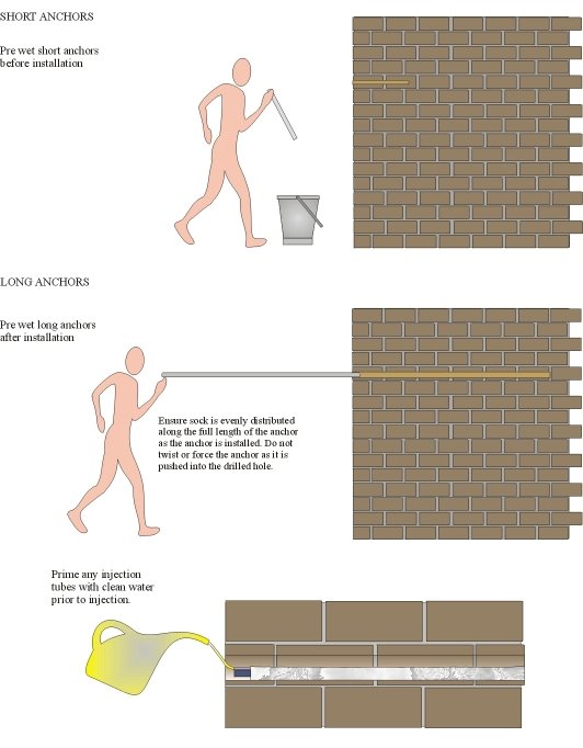
- Immediately prior to insertion wet the anchor completely with clean water, and position the sock evenly along the length of the anchor.
- Long anchors should be wet after insertion into the bore hole by injecting clean water through the anchor injection tube.
N.B. Do not allow the sock to remain completely saturated with water for a long period as this may cause the fabric sock to shrink - Place the anchor in the bore hole and carefully push the anchor in lifting it over any fissures or voids, do not force or twist the anchor into the hole.
- Install the anchor to within 50mm (2”) of the face of the brickwork (do not push completely in yet.)
- Studding and solid bar (rebar) anchors, the normal installation still apply, but the following methods needs to be adopted to facilitate the installation.
- When inserting the anchor ensure that the injection tube is towards the top of the borehole – NEVER force or twist the anchor into the hole.
- When mixing the grout, the water content can be increased by up to 10% e.g., 25 kg (56 lbs) of grout to 5.5 litres (1.58 US Gal) of water+ 10% = 6.05 litres (1.75 US Gal).
- Cut mastic nozzle to fit over the injection tube (not inside).
- Inject the anchors through the injection tube with clean water just prior to injecting the grout.
- When inflating anchor slowly rotate the anchor in the borehole to facilitate the grout flow and to ensure the anchor is centralised on completion.
- Maintain the pressure until all the grout milk has been expelled.
Cold Weather Grouting
The installer shall ensure that the minimum temperature of the grout at the time of injection is 7°C (45°F) and the temperature of the injected grout does not fall below 5°C (41°F) for a period of 24 hours from the beginning of inflation.
If this is impractical cold weather procedures must be adopted with the consent of Cintec™ International.
The cold weather procedures are as follows:
- The pressure pot and delivery hose should be lagged with a suitable insulating material.
- The grout, anchors and pressure pot must be stored in a container or room with a temperature of no less than 10°C (50°F).
- The clean water used for mixing must be within the temperature range of 15°C-20°C (59°F-68°F).
- The bore hole temperature must not be below 0°C (32°F) and no ice crystals must be present on the surface of the bore hole.
- A suitable shelter needs to used for the mixing process.
- A screen needs to be erected around the installation area to avoid any wind chill.
- NB -After drilling the bore hole install a suitable plug to maintain a constant core temperature.
- Insert the anchor in the bore hole just prior to inflation (as per normal installation methods)
- NB – Allow the outside temperature to rise before injecting the grout, i.e. do not inflate first thing in the morning or last thing in the afternoon.
- Mix the grout as per instructions using the heated water and sieve into the insulated pot.
- Inflate the anchor as normal.
- NB – Immediately after inflation install insulation in the front of the bore hole. [Using an expanding foam or similar insulation].
Please note that these procedures must be carried out with extreme care and should not be used unless a representative fromCintec™ International is present.
Hot Weather Grouting
- In very hot climates the maximum temperature of the grout at time of injection must not exceed 20°C (68°F).
- If the temperature exceeds this the clean water used for mixing must be cooled to 15°C (59°F).
- NB – The pressure pot and the bore hole must be shielded from direct sunlight, in extreme conditions the pressure pot must be placed in a vat of cooled water or ice.
Problems Encountered During Inflation
Grout blockage can occur in the hose and control valve if left in direct sunlight or the mixed grout has not been sieved correctly.
The anchor will not inflate if the sock has been ripped during installation. Remove the anchor from the bore hole and check the sock, small tears can be repaired and the anchor re-installed, if the damage is more severe remove the grout and fabric sock and wash off the anchor completely. Notify Cintec™ International Ltd who will arrange a repair procedure.
Anchor fails to fill only partially fills, fails to reach surface of bore hole.
There are a number of factors to consider here, check all the following possibilities:
- Grout mixture too thick either by incorrect mixing or outside the working time of the mixed grout (usually between 45 minutes and 1 hour, dependent on conditions).
- Grout has passed its shelf life. Check date on side of bag.
- Anchor installed in a larger diameter bore hole than the anchor was designed for. Check original order.
- Large voids are present tensioning the sock at the front of the anchor. A larger sock may be required.
- Insufficient pressure in the pot. Shut off the air from the compressor and check that the pressure pot is maintaining a constant pressure. If it is dropping, check for leaks. Remember, what is shown on the gauge is not necessarily what is in the pot because the air can be passing into the pot and straight out through any leaks.
- The sock has twisted during installation, preventing the grout passing the twist. Do not force or twist the anchor while inserting
- Sock not distributed evenly before insertion therefore there is too much sock at the front of the bore hole preventing complete inflation.
- Failure to wet sock, this is very important in porous substrates and in dry/hot weather conditions.
Salient Points to Consider Before Ordering Anchors
This is a designed anchoring system, therefore as much information as possible about the type of substrate and possible voids etc. is required to enable us to manufacture the exact anchor to meet your requirements.
The minimum embedment depth of any anchor is 75mm (3”) unless test anchors have been installed to determine the load achievable with a reduced embedment.
The maximum length of an 8mm (5/16”)or 10mm (3/8”) anchor in a 20mm (3/4”) hole is 500mm (20”).
For lengths between 500mm (20”) and 1000mm (39”) a 24mm (1”) hole is required using a 10mm (3/8”) chs anchor.
The general rule is that the bore hole must be twice the diameter of the anchor body utilised. This is only applicable up to certain lengths and the hole size must be increased on longer anchors.
The guidelines are as follows:
| 8mm (5/16”) chs | 20mm (3/4”) bore hole | up to 500mm (20”) |
| 10mm (3/8”) chs | 20mm (3/4”) bore hole | up to 500mm (20”) |
| 10mm (3/8”) chs | 25mm (1”) bore hole | up to 1000mm (39”) |
| 10mm (3/8”) chs | 32mm (1 1/4”) bore hole | up to 2000mm (6’6”) |
| 15(5/8”) x 15(5/8”) shs | 32mm (1 1/4”) bore hole | up to 3000mm (9’9”) |
| 20(3/4”) x 20(3/4”) shs | 40mm (1 1/2”) bore hole | up to 3000mm (9’9”) |
| 30(1 3/16”) x 30 (1 3/16”) shs | 60mm (2 1/2”) bore hole | up to 4000mm (13’0”) |
| M10 (3/8”) studding | 32mm (1 1/4”) bore hole | up to 1000mm (39”) |
| M12 (1/2”) studding | 25mm (1 1/4”) bore hole | up to 1000mm (39”) |
| M16 (5/8”) studding | 40mm (1 1/2”) bore hole | up to 3000mm (9’9”) |
| M20 (3/4”) studding | 50mm (2”) bore hole | up to 4000mm (13’0”) |
Care of Anchors and Grout
The anchors and fixings are supplied with the correct amount of grout. Care must be taken not to waste grout. The anchors, fixings and the grout should be stored safely away from all work areas until needed.
Store grout in a dry place off the ground. NEVER allow the grout to become damp, or wet, or store in a place where the temperature can drop below 5ºC (41°F).
NB – The marriage of steel and fabric is very delicate and the anchors must be treated accordingly to ensure that no damage to the fabric sock occurs. DO NOT leave anchors lying around on the ground or on scaffolding. NEVER use anchors to test the hole depth.
Notes and Method Statement for Grout Filled Cartridges
- Use a small clean container e.g. plastic paint bucket and measuring jug.
- Remove back plug from container, pour grout contents into the mixing pot, gradually add small amount of clean water stirring until the consistency is a smooth medium thick cream.
- Mix for at least four minutes with a whisk then allow to stand for a further four minutes and whisk again.
- Pour the mixed grout back into the container and replace back plug securely.
- Remove nozzle to remove inner plug and replace nozzle.
- Place container into master gun, insert nozzle into back of anchor and proceed to pump.
- Pump until trigger is stiff, hold for 10 seconds, release safety catch and withdraw slowly from the anchor.
- Repeat the same process for each anchor.
NB: If you use a re-usable mastic/grout gun. These hold approximately 0.5 litre (0.87 pint) of grout. Therefore 220 ml (0.35 pint) of water to 1 kg (2.2 lbs) of grout is enough for one fill which will pump 5 RAC standard anchors. The water ratio can be altered slightly dependent on weather conditions. Mix as above for at least four minutes; allow to stand for four minute; mix for a further minute.
Stages
| Step 1 | Measure 220 ml (0.35 pint) of water into a clean container and slowly add 1 kg (2.2 lbs) of grout, whisk thoroughly for four minutes and allow to stand for a further four minutes and whisk again. The mixture should be smooth and creamy with no lumps |
| Step 2 | Pour mixed grout into front of gun and replace tap assembly. |
| Step 3 | Turn off tap and pressurise gun. |
| Step 4 | Push nozzle on anchor and open valve when anchor is full keep pressure on for 10 seconds, close valve and remove nozzle. |
If you use a metal grout gun grout on occasions collects at the base. To overcome this problem do not fully empty the gun, and remove excess grout. Swill all parts in a clean bucket of water between each mix.
*NB: Metal hand grout guns must be washed and fully cleaned and thoroughly dried, after use.
DO NOT oil cylinder as this would contaminate the grout.
Failure to carry out above will result in rusty equipment.
Health and Safety Data Sheets Additional Notes for North American Contractors Health and Safety at Work : North America
All work must be carried out in accordance with Federal, State/Provincial laws, by-laws and all relevant building regulations.