The Cintec™ anchoring system provides a fast and efficient technique to stabilise earth-retaining structures. From centuries-old town walls to rail retaining walls—even in ancient ruins in Israel—Cintec™’s ground anchoring system has provided adaptations for each project’s unique requirements whilst remaining sensitive to the original architecture.
In earth-retaining structures, ground anchors provide the main reinforcement; other anchors can also be used to provide additional consolidation.
The Cintec™ anchoring system for ground anchors is essentially the same concept. The first step is assessment to develop the most effective and efficient design, including the type of anchors to be used and where they should be installed. Investigative cores are taken to determine the wall thickness, type of material within the wall and the consistency of the retained material.
Once a design has been established, the system is ready for installation. A stainless steel reinforcement bar in is inserted into a fabric ‘sock’ and the entire assembly is inserted into a pre-drilled oversized hole. The sock is injected with Cintec™’s cementitious Presstec™ grout, and the grout fills in the voids around the steel bar, efficiently fixing everything in place. The sock’s close weave permits small amounts of the grout milk, which is a cementitious bonding agent, to seep into the surrounding ground to further strengthen the fixing.
Unlike conventional mechanical anchors, the Cintec™ anchoring system benefits from fissures and voids—these are filled by the flexible grout-filled sock to create a strong mechanical bond. Additional information can be found at http://www.earthretainingwalls.com.
1. Designing
General Design Considerations
Where ground anchors are being utilised, the designer should give careful consideration to the following points:
- Detailed field and laboratory tests to establish soil characteristics.
- Full-scale load tests to confirm engineering predictions.
- Assessment of consequences of potential long-term creep.
- Overall length of anchor, fixed anchor length, failure planes.
- Effects of anchor groups if anchors closely spaced
- Likely stress losses due to tendon relaxation.
- The free anchor length can be released from the grout by use of smooth tubes forming the second barrier of corrosion resistance, thus avoiding stressing ground close to structure.
- The factor of safety to be applied.
- Reference should be applied to the British Standard BS.8081 : 1989 or other appropriate document for advice on usage and design.
2. Testing
In-Situ Load Testing The Cintec Ground Anchor
A feature of the Cintec™ system is that a choice of connections can be achieved with regard to fixing to structure. Traditional anchor head details may be used where periodic re-stressing or monitoring is required. Where the structure is suitable, the anchor may be bonded to the material as a permanent fixing, without the requirement for surface apparatus.
The general conditions at each location will dictate the design stresses to be used in assessing the ultimate capacity of an individual anchor. Where laboratory tests are not available, full-scale in situ tests are required to establish the lower bounds of the substrate capacity.
A minimum fixed anchor length of 3 metres (9.8 feet) is recommended to account for local variables in substrate conditions.
In order to reduce the possibility of long term ground creep, factors of safety should be applied. These factors should be of the order of 3 to 4 dependent on soil consistency, life expectancy and their importance to the structure.
The fixed anchor length must be located beyond the critical zone, such as the wedge failure, slip circle, rock discontinuities in order to be effective. The free anchor length will depend upon the geometry of the location.
The anchors can act as a restraint, only accepting load if movement occurs, or they can be pre-stressed to a set load to provide an active force.
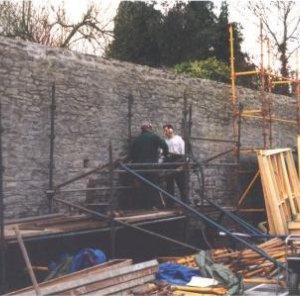
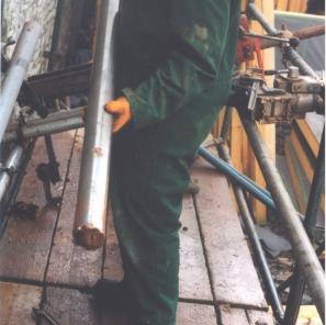
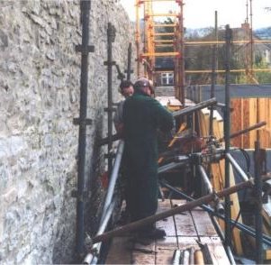
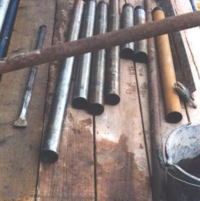
3. Solutions
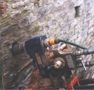
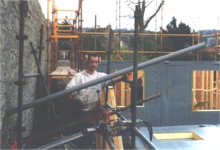
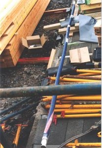
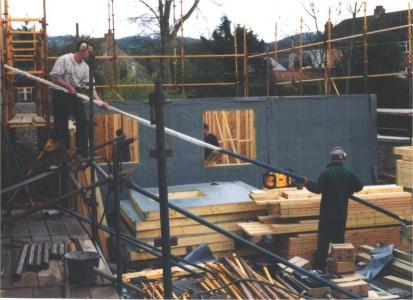
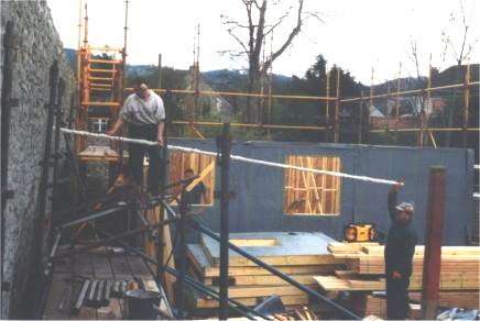
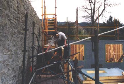
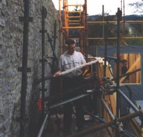
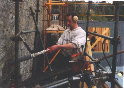
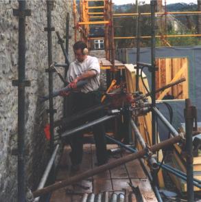
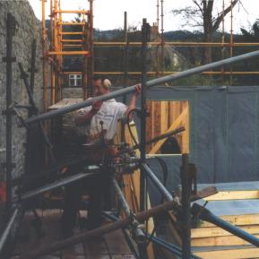
The following pictures show the process of drilling for, installing and grouting the Cintec™ ground anchors. Click on any of the images to make larger.