


The Cintec™ anchoring system is simple and easy to use, with fast installation and minimal cleanup. But its advantages go far beyond ease of use.
Finite/discrete element models for assessment and repair of masonry structures
D. RJ. Owen, D. Peric and N. Petrinic
Department of Civil Engineering, University of Wales Swansea, UK
CL. Smokes
Gifford and Partners, Southampton, UK
P.J.. James
CINTEC International Ltd., Newport, UK
Abstract
The predictive modelling of masonry structures represents a challenge due to their semi-discrete and composite nature. This paper presents an approach to modelling which considers the composite action of individual masonry components as an alternative to macro-modelling based on a homogenised continuum. A primary aim of the current research is to develop computational procedures for assessing the remnant strength of damaged masonry structures and to examine the efficiency of alternative repair strategies. Technical issues considered in the paper include the coupling of polygonal discrete elements for simulating the behaviour of masonry structures with circular discrete elements for representing geotechnical fill material. The approach adopted for parallel solution is also summarized.
Introduction
The ultimate objective of the work described in this paper is to develop industrially applicable computational procedures to assess alternative repair strategies for damaged masonry structures. In many Stances, structures which have been damaged can be successfully repaired by the insertion of anchors, use of prestressing systems, etc. For relatively modern structures the decision to repair, rather than demolish, may be based on economic considerations, but for historic structures the use of remedial techniques becomes a cultural necessity. Currently, appropriate stitching patterns are selected on the basis of previous experience and a major aim of the research is to provide a rational approach to determining an efficient and near-optimal anchor arrangement In this way, an industry standard simulation capability will be provided to aid decision making in quantifying the remnant structural integrity of masonry structures and to examine optional remedial actions.
The predictive modelling of the behaviour of masonry structures, particularly in the non-linear range, remains a challenge, due predominantly to their semi-discrete and composite nature. An adequate computational model must include the fundamental mechanisms that characterise the composite action: (i) sliding along a bed or bead joint at low values of normal stress, (ii) cracking of the masonry units (bricks, blocks, etc.) in direct tension, (iii) diagonal tensile cracking of masonry units at values of normal stress sufficient to develop frictional behaviour in the joints and (iv) splitting of units in tension as a result of mortar dilatency at high values of normal stress. Further aspects which may require consideration include the treatment of reinforcement and/or prestressing in composite construction techniques or repaired structures. To date, most computational predictions have been based on a macro-modelling approach, in which attempts are made to incorporate some or all of the phenomena described above within a continuum description; employing homogenisation concepts to produce a smeared representation of the brick/joint action and classical plasticity concepts to model the tensile/compressive failure of the resulting composite. Such a modelling strategy has been dictated both by the limits of available computing power and the lack of maturity of other semi-discrete computational techniques.
Whilst considerable fundamental information can be derived from solutions based on a continuum approach, a more natural treatment of this class of problem is offered by use of discrete element methods. The use of discrete elements originated in geotechnical and granular flow applications and are based on the concept that individual material elements are considered to be separate and are (possibly) connected only along their boundaries by frictional/adhesive contact. With present day computational power large scale discrete element models can be considered and for industrial applications in the field of rock blasting, etc. 10-50,000 elements are routinely employed.
Earlier work on discrete element techniques was based on the assumption that each element was rigid, but later extension to include local deformation has permitted a more rigorous treatment of both the contact conditions and fracture requirements. The incorporation of deformation kinematics into the discrete element formulation has also led naturally to a combined finite/discrete element approach in which the problem is analysed by a combination of the two methods [5,14,16].
In a finite/discrete element analysis the main issues which require consideration, for both dynamic and quasi-static behaviour, are: (i) Appropriate element modelling of the continuum and discrete regions with a view to incorporating the deformation mechanisms necessary to model stress, stain and frictional contact/adhesive conditions, (ii) The inclusion of elasto-plastic/viscoplastic behaviour in both the finite and discrete elements, (iii) Algorithms for treatment of the progressive fracturing of elements, (iv) Detection procedures for monitoring contact between discrete elements and the continuum regions and (v) Representation of frictional/adhesive contact conditions for contacting elements.
The first phase of this ongoing study has embraced recently developed numerical techniques for solving problems in applied mechanics which exhibit large discontinuous geometrical and nonlinear material behaviour. The technical developments considered in this paper concentrate on coupling of polygonal discrete elements for simulating the behaviour of masonry structures with circular discrete elements for representing geotechnical fill material for masonry arch bridges, etc.. The approach being currently pursued to enable the parallel solution of these CPU intensive problems is also summarized.
Computational Framework
In order to simulate the complete behaviour of large systems of discrete interacting bodies, the applied numerical technique should consider three important aspects [14]: (i) the detection of contacts, (ii) the representation of contact interaction, and (iii) the behaviour of solid material. In this study, the behaviour of solid material is analysed using the finite element method [1,2,10,15,20], except for round shaped bodies whose deformations can be approximated solely on the basis of the deformation in the close vicinity of their contacting surfaces. Furthermore, an exceptionally efficient geometric intersection algorithm has been adapted to meet the requirements of computational speed for the treatment of multi-body contact problems. In addition, the method for evaluation of contact forces, based on a penalty approach, has been improved to include the material and geometric properties of the contacting bodies, leading to a “facet-to-facet” contact interaction technique with respect to the finite element discretisation of contacting surfaces.
Geometric idealisation
The composite action of distinct interacting bodies is simulated numerically by applying the combined discrete/finite element method. Several modifications of the well established finite element method have been performed to increase its robustness, always bearing in mind the permanent demands for calculation speed and the final quality of results. In addition, by applying advanced “soft-rigid” single circular elements (Figure 1) for geometric idealisation of round shape bodies an efficient technique for the treatment of granular media has been devised.
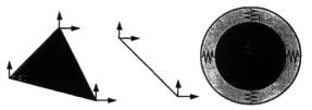
Figure 1. Basic geometric entities – finite/discrete elements
for 2D spatial discretisation of masonry structures.
Some results obtained by applying the numerical techniques developed are illustrated in Figure 2.
The implemented geometric modelling techniques [3] are capable of automatically handling any changes which occur in the modelling domain as a result of frictional sliding or progressive fracturing.
Material models
Generalised elasto-plastic or elasto-visco-plastic material models, combined with several different failure models, are applied in order to numerically simulate the fracturing phenomenon [14]. The solid media fracturing technique is based on a strain softening formulation which utilises standard fracture mechanics concepts of energy release required for crack opening. Alternative techniques are being currently considered in order to control the evolution of the failure surface via tensile and/or shear fracture energy densities.
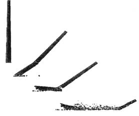
Figure 2.(a). Controlled demolition of a chimney.
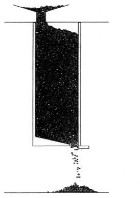
Figure 2.(b). Silo flow.
Contact models
The numerical techniques for simulating both frictional sliding and fracturing result from the latest developments in continuum based computational plasticity [6,9,19]. This paper concentrates on a solution method for coupling of polygonal and circular discrete elements in masonry units, arch bridges and similar structures.
The penalty method based on contact surface deformation theories [4,8], is employed to determine the contact tractions arising from contacts between the bodies under consideration. The overlap – which is physically inadmissible – is assumed to represent the deformation of the contact region. The surface tractions are determined by solving the equilibrium and compatibility equations at the interface.
In the penalty method, a penetration function defined as follows
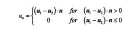
(1) is applied in order to define which parts of the surfaces are in contact as well as to determine the intensity of tractions arising from contact. Two contacting bodies in motion can also experience some relative tangential displacement which can be expressed as follows
![]()
(2) where t is the vector in the plane previously defined by its normal n, while u1 and u2 represent the displacements of the points P1 and P2 respectively (Figure 3).
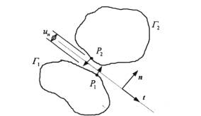
Figure 3. Contact between two bodies.
The decomposition of the total relative displacement between the two points on interacting boundaries determines a convenient decomposition of the total contact traction (?) as follows
![]()
(3) in contact between In view of the finite element method which is applied to describe the behaviour of the solid material, the resultant force transmitted from one surface to another through the area of contact is obtained by integrating the contact tractions as follows
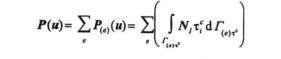
(4) where NI represents the element shape functions and determines the part of the contact surface associated with element e.
The normal component of the contact force arising from contacts between two circular disks is evaluated using the analytical solution [8,17]. A special case of the contact between two circular disks arises when one of the disks’ radii becomes infinite, thus representing a flat surface. Moreover, this case prompts the question of how to handle contacts between some arbitrary shaped bodies. Since the finite element method is applied to determine the behaviour of solid material, the bodies’ boundaries are represented by finite facets. In the case of linear 2D elements these facets are represented by line segments. During contact detection each facet is treated as an independent geometric entity. The contact tractions are evaluated with respect to the contact zone deformability potential similar to the volume potential [13] but devised from the deformation theory [4] and then assembled to the boundary nodes.
When a contacting disk touches more than one segment of a polygonal boundary the contact tractions are divided according to the overlap area ratio as follows
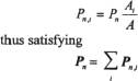
where A represents the overlap areas as illustrated in Figure 4. The direction of the resulting contact force is defined by the position of the centroid for the associated overlap area.
Parallel Processing Strategies
The degree of natural algorithmic concurrency in the solution of transient dynamic problems by central difference explicit time integration is high due to the use of lumped mass procedures, which leads to an uncoupled equation system whose solution is trivial. The bulk of the computational costs within a time-step involves the evaluation of the internal element forces and therefore the major benefits to be derived from parallel processing of the time integration procedure emanate from this phase of analysis. Fortunately, this is an element based operation and the task can be parallelised by simply performing the computation concurrently for different groups of elements on separate processors using domain decomposition procedures [7] which provides high efficiency and solution speed-up for this class of problem. The development of this parallel strategy has been undertaken on both SG Power Challenge and Cray YMP-EL98 shared memory parallel machines and implementation has been facilitated by use of a purpose built general library developed specifically to port code to parallel platforms [12]. The code, which incorporates both PVM and MPI message passing protocols, provides easy linking between the high level application code (the finite element analysis) and SMP or MPP hardware environments. This software tool contains both a real-time graphics window to monitor the performance of a parallel code and an a posteriori performance analysis tool.
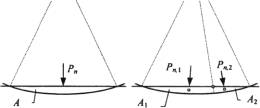
Figure 4. Distribution of forces circular and polygonal elements.
When a large degree of inter-element contact occurs, as is the case with discrete elements, parallelisation becomes more difficult as contact conditions continually change. A naïve contact detection search method would require the checking for contact between each facet from a given set and each and every other facet listed after the facet under consideration. This method becomes extremely expensive for a large number of facets and several algorithms [e.g. 17] have been proposed to solve the equivalent problem with a computational expense proportional to
![]() (7)
(7)
Such a contact detection search algorithm, based on the alternating digital tree (ADT) geometric intersection search algorithm [3], is implemented~ to drastically reduce the number of operations required to determine all contacts between the facets under consideration. The implemented algorithm is divided into four phases:
(i) location mapping, (ii) space bisection, (iii) bounding box intersection search, and (iv) local resolution.
In the location mapping phase, the locations of all facets in nD space are mapped into their corresponding point representations in 2nD space by means of their bounding boxes. An alternating binary tree based on space bisection is then built to embody the information on relative positions between the facets under consideration. A corresponding bounding box geometric intersection search is then performed to create the short lists of possibly contacting facets for each target facet under consideration. The local resolution phase is further divided according to the type of the contacting facets and its only role regarding the contact detection search is to remove from further consideration those contacting pairs which do not stand a chance of becoming in contact before the next neighbourhood update.
The parallel processing version of the above algorithm undertakes the following steps:
- each processor builds an ADT with its own boundaries
- each processor searches within its own tree followed by a search of the other processors’ trees
- the contact forces are solved avoiding the repetitive computation of forces between bodies on different processors.
Figure 5 presents the solution of 100,000 contact facets on a SGI Power Challenge. For up to 7 processors, the efficiency obtained is always greater then 1, being 1.12 when running with 3 and 4 processors, with a respective speedup of 3.36 and 4.48. This apparent phenomenon, termed “superlinearity” is a common occurrence in parallel processing and is related to the definition of speedup.
Application To Arch Bridges
The potential of the combined finite/discrete element methodology for solving industrial scale problems is appraised by the solution of two examples. European Commission Directive 96/58IEEC which seeks to harmonise transport policy with regard to heavy goods vehicles has resulted in the necessity to assess the adequacy of a substantial number of existing bridges. Masonry arch bridges are assessed in a rather conservative manner because of their complexity and, in some cases, their historic value. Experimental and field tests are still comparatively far more expensive to undertake then numerical simulations, thus encouraging further improvement of existing numerical predictive techniques.
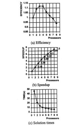
Figure 5. Performance of parallelisation of contact search algorithm
Masonry arch bridge with backfill
As an illustration of the capabilities of discrete/finite element numerical techniques for predictive modelling of situations involving masonry units, back-fill and geotechnical foundation material, a hypothetical masonry arch bridge with granular back-fill is first considered. The problem is treated as a combined finite/discrete element problem with the masonry blocks being represented by deformable discrete elements in frictional contact, the fill material by spherical discrete elements and the foundation medium beneath the central pier modelled as a Mohr-Coulomb material. The idealised two span bridge was subjected to abnormal vehicular loading in order to determine the load distribution in the back-fill medium and in the arches. The results obtained are illustrated in Figure 6 where the vertical stress distribution is shown for two positions of the traversing load. The load transfer paths through the granular fill can be clearly seen.
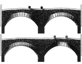
Figure 6. Vertical stress distribution in the back-fill medium and the arches.
Arch bridge with anchor stitching system
This example considers the performance of a three ring arch bridge, firstly unstrengthened and secondly when reinforced with the Cintec™ anchor stitching system. Both arches were constructed and tested to destruction under controlled conditions at the Transport Research Laboratory, UK. Each arch was constructed with a layer of wet sand between the three rings to simulate ring separation (delamination). A schematic illustration of the arch, together with the general arrangement of the Cintec™ anchors, is shown in Figure 7.
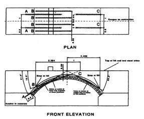
Figure 7. Arch strengthened with Cintec™ anchor system.
Each anchor is modelled as an elasto-plastic steel bar and the grouted bond with the masonry is simulated by prescribing a (non-linear) shear stress/strain relation, whose parameters are determined from laboratory anchor pull-out tests.
The test load was applied at quarter span in 1 tonne increments with failure occurring in a ductile manner by crushing of the bottom brick at the crown which, for the strengthened arch, led to the formation of the first hinge at 28 tonnes. During loading to collapse the bottom ring fell away but the remainder of the arch remained held together by the anchors. The arch ultimately failed in a four hinge mechanism. The failure loads for the unstrengthened and reinforced arch were 20 tonnes and 41 tonnes respectively. The deformation of the strengthened arch just before the bottom ring fell away is illustrated in Figure 8.
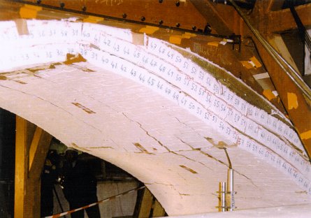
Figure 8. Strengthened arch just before bottom ring fell away.
Figure 9 (a) shows the finite/discrete element idealisation of the unstrengthened arch and Figure 9.(b) depicts the deformation just prior to collapse. The displacement under the load line with increasing load is shown in Figure 10, where the prediction for the unstrengthened and reinforced cases are compared. An excellent correlation between the numerical prediction and experimental observation for the peak loads is evident.
Concluding Remarks
The combined discrete/finite clement method presented in the paper offers an alternative approach to predictive modelling of the failure assessment, and subsequent repair, of masonry structures. As such, the work represents ongoing research and further development is necessary to ensure the robustness and industrial applicability of the methodology. A further development which is currently in progress involves extension of the procedure to fully three dimensional problems. This clearly extends the scale of the problems to be solved, necessitating the use of parallel processing techniques, but permits a more realistic simulation of the action of a wide range of masonry structures. In view of the complex geometrical configurations existing in an evolving finite/discrete element analysis, the use of visual tools for interpreting the results is mandatory. In addition to employing the more usual on-screen representation of 3D objects, the use of virtual reality techniques to provide a fully immersive environment for the interpretation of results is becoming increasingly attractive and realisable. Currently, appropriate data structures, etc. are being developed to permit interfacing the results of the simulation of masonry structures within a VR environment This will allow visualisation of damage, cracking states, stress distributions, etc. in an interactive and stereoscopic manner.
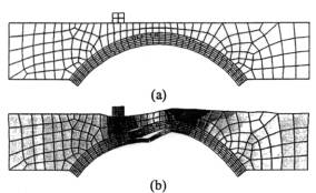
Figure 9. (a) Finite/discrete element idealisation, (b) Displacement pattern close to collapse.
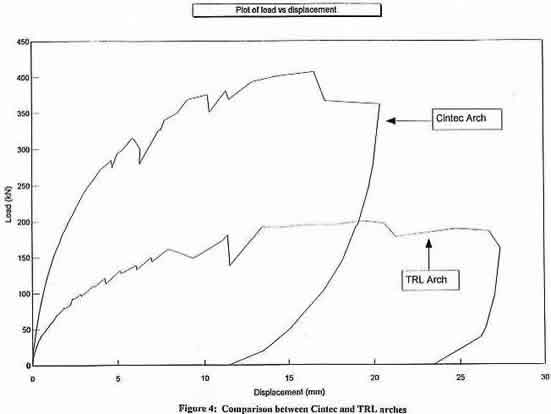
Figure 10. Load-Displacement predictions for the unstrengthened and reinforced arches.
References
- Bathe, K.J., Wilson, E.L.: Numerical Methods in Finite Element Analysis; Prentice-Hall Inc.; New Jersey; 1976
- Bclytschko, T., An Overview of Semidiscretization and Time Integration Procedures; Computational Methods for Transient Analysis; Eds. Belytschko, T. and Hughes, T.J.R.; p. 1-65; Elsevier Science Publishers B.V.; 1983
- Bonet, J., Peraire, J.: An Alternating Digital Tree (ADT) Algorithm for 3D Geometric Searching and Intersection Problems; Int. J. Num. Meth. Engng.; Vol. 31; p. 1-17; 1991
- Boussinesq, J., Application des Potentials à l’etude de l’équilibre a du mouvement des solicits élastiques; Gauthier-Villars; 45; p. 180; Paris; 1885
- Cundall, P.A., Hart, RD.: Numerical Modelling of Discontinua; DEM 1st U.S. Conference; CSM Press; Golden, Colorado; 1989
- Dowding, C.H., Zubelewicz, A., O’Connor, K.M., Belytschko, T.B., Explicit Modelling of Dilation. Asperity Degradation and Cyclic Seating of Rock Joints; Computers in Geotechnics; Vol 11; p. 209-227; 1991
- Paw, G.F., Parallel processing procedures for finite element analysis.; Ph. D. Thesis, University of Wales, CIPHJ192/96
- Hertz, H., Über die Benührung fester elastisher Körper, J. mine und angewandte Mathematik; Vol. 92; p. 156-171; 1882
- Laursen, T.A., Simo, J.C., On the formulation and numerical treatment of finite deformation frictional contact problems; P. Wriggers, W. Wagner, eds.; Springer; Berlin; 1991
- Naylor, D.J., Pande, G.N., Simpson, B., Tabb, R.: Finite Elements in Geotechnical Engineering; Pineridge Press Ltd.; Swansea; 1981
- Loureriço, P.B., Rots, E.G., Blaauwendraad, J., Implementation of an interface cap model for the analysis of masonry structures; Proceedings of EURO-C 1994 International Conference on Computer Modelling of Concrete Structures; Innsbruck; 1994
- Macedo, J.P., Owen, D.R.J., A general parallel porting support library, Internal Report, Dept. Civil Engineering, University of Wales Swansea, 1996
- Munjiza, A., Owen, D.R.J., Crook, A.J.L., Energy and momentum preserving contact algorithm for general 2D and 3D contact problems; COMPLAS, 4th International Conference on Computational Plasticity; Barcelona; 1995
- Munjiza, A., Owen, D.RJ., Bicanic, N., A combined Finite/Discrete Element Method in Transient Dynamics of Fracturing Solids; Engineering Computations; 12; p. 145-174; 1995
- Owen, D.R.J., Hinton, E., Finite Elements in Plasticity: Theory and Practice; Pineridge Press Ltd.; Swansea; 1980
- Owen, D.R.J., Munjiza, A., Petrinic, N., Bicanic, N., Reinforcement Concrete Models for Combined Finite/Discrete Analysis; Proceedings of the Fifth International Conference on Reliability of Finite Element Methods for Engineering Computations; p. 142-15 1; Amsterdam, The Netherlands; 1995
- Taylor, L.M., Preece, D.S., Simulation of Blasting Induced Rock Motion Using Spherical Element Models; DEM 1st U.S. Conference; CSM Press; Golden, Colorado; 1989
- Underwood, P., Dynamic Relaxation; Computational Methods for Transient Analysis; Eds. Belytschko, T. and Hughes, T.J.R.; p. 245-265; Elsevier Science Publishers B.V.; 1983
- Wriggers, P., Scherf O., Adaptive Finite Element Methods for Contact Problems in Plasticity; COMPLAS, 4th International Conference on Computational Plasticity; Barcelona; 1995
- Zienkiewicz, O.C., Taylor, R.L., The Finite Element Method – Volume 2: Solid and fluid mechanics dynamics and non-linearity; McGraw-Hill Ltd.; London, 1991