


Parapet Wall Strengthening
No two masonry arch bridges are the same, and this also applies to their parapet walls. The requirements specified for individual walls can differ considerably and must reconcile a variety of needs. These may include impact containment, vehicle redirection, the protection of others in the vicinity, compatibility with the masonry structure as a whole, as well as the visual appearance of the strengthening solution implemented.
The Cintec™ anchoring system provides a highly versatile method of internal structural reinforcement that is tailored to meet the specific requirements of each parapet wall. This service, known as Paratec is backed by extensive research and development from advanced computer modelling, practical testing and experience built up from numerous strengthening projects. The Paratec system can strengthen a masonry wall while remaining sensitive to the original architecture and without any narrowing of the road way.
The Anchor
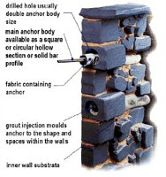 The system comprises a steel bar enclosed in a mesh fabric sleeve, into this a highly specialised grout is injected under low pressure. This is a Portland cement based product, containing graded aggregates and other constituents which, when mixed with water, produce a pumpable cementitious grout that exhibits good strength without shrinkage. Installation is by precisely drilled holes using wet or dry diamond coring technology. The flexible sleeve of woven polyester restrains the grout flow and expands up to twice its original diameter moulding itself into the shapes and spaces within the walls. This provides a strong mechanical bond along the entire length of the anchor dispensing with the need for external anchor plates.
The size and type of steel anchor, the strength of grout and the diameter of the hole can all be varied to provide the required design parameters and to provide an appropriate stiffness compatible with the masonry.
Research and Development
 The comprehensive service offered by Paratec include advanced computer modelling techniques that simulate the effects of a vehicle impact upon a specified masonry wall. Working in conjunction with both software specialists and consulting engineers, Paratec utilises an advanced dynamic software incorporating a discrete element analysis technique that enables the behaviour of parapet walls to be accurately predicted under various circumstances.
Practical Testing
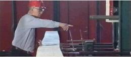
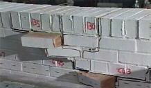
Dynamic full-scale parapet wall tests were undertaken in the heavy structures laboratory at Tyne-Tees University. The tests clearly demonstrate the robustness of parapet walls reinforced with Cintec™ masonry anchors. The walls were impact loaded using a falling weight test rig designed to generate the force/tme history of an actual vehicle impact test that had previously been recorded and analysed at MIRA.
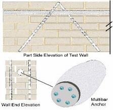
 In this test, the Cintec™ reinforcement used was a 19.5 meter (64 feet) high-yield MS multibar anchor comprising six individual stainless steel bars of 8mm in diameter. This was installed 370mm below the top of the wall.
Raking anchors were also installed in pairs at 30° to the vertical. These were 100×3 x8mm diameter multibar anchors encapsulated in a 40mm diameter sock and installed in a 50mm diameter hole.
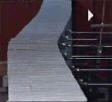
Although the bridge was shunted by the force of the impact, it remained intact with no significant spalling. The picture above shows the wall face opposite to the point of impact after two consecutive tests.
Prestressing Understrength Walls and Parapets
Prestressing Understrength Walls And Parapets
Patrick Jansen and Dr Graham Tilly
Paper Presented To ‘Structural Faults And Repairs – 1999’
Prestressing Understrength Walls And Parapets
Patrick Jansen and Dr Graham Tilly
Gifford and Partners
Canton House, Ringwood Road
Woodlands
Southampton, S040 7HT
Introduction
There are many brick walls and parapets, supported on elevated structures and located at the sides of roads and railways, that are now over 100 years old, some over 150 years, and in need of maintenance. One of the main causes of deterioration is through ageing and degradation of the mortar which is invariably lime based in these older structures.
The walls must be able to withstand wind loading, and where they are located beside roads or railways, there are extra windage effects caused by passing traffic. Additionally, there are traffic induced vibrations which can exacerbate the live loading and accelerate deterioration of the walls by loosening the old mortar. ft is also not uncommon for walls, particularly those beside railway lines, to experience additional dead load effects due to utility pipes being bolted on, see Figure 1.
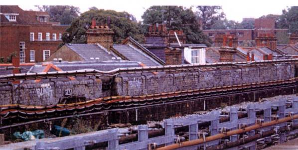
Figure 1 Parapet wall with bolted on utilities
Currently, old walls are failing strength assessments and it is necessary to undertake remedial measures by a suitable method. In addition many older walls are prone to inadequate stability. Differences in flexibility between the walls and their supporting structure, thermal movements, lateral loading effects, bed joint degradation and loss of adhesion can all lead to the walls becoming detached from their substrata. The supporting structure’s contribution towards stability is thus lost, resulting in a reduced factor of safety for stability.
Any strengthening proposal must satisfy the requirements for both strength and stability as necessary. This papers presents such a strengthening solution using Cintec™ anchors, a system of post-tensioning that has been tailored to meet the requirements of brick walls. An in situ test to confirm the performance of a post-tensioned 100 year old wall in the field is described.
Options For Strengthening
The appearances of old brick walls do not necessarily have intrinsic value on their own, but taken alongside other structures such as adjacent bridges and buildings of similar age, the collection often merits heritage status. It follows that methods of refurbishment and strengthening should be acceptable in a cosmetic as well as structural sense.
In the normal course of events, deep raking out and repointing of the mortar joints using a stronger cementitious material is the most straightforward refurbishment. The lateral bending strength of the wall can be raised some 70 per cent using this method. However, using conventional methods of analysis and assessment, it is difficult to justify that such repairs provide adequate strength and factors of safety. Furthermore, repointing is a time consuming activity made additionally expensive by costs of access and the need to have lane closures or track possessions to satisfy safety requirements. In any event, repointing is unlikely to satisfy the requirements for stability.
In situations where walls are located on top of retaining structures (a fairly common occurrence), strengthening is sometimes carried out by bolting vertical channel-section steel girders to the brickwork and retaining structure, see Figure 2. This is an unsightly method requiring regular maintenance painting and unpopular with heritage bodies. Furthermore, it is often impracticable to fit the girders when utilities are bolted to the walls.
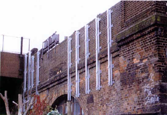
Figure 2 Externally strengthened wall
Post-tensioning the brickwork into the substructure provides a mode of strengthening having none of the above objections. It is quick to carry out, leaves no external evidence on the brickwork and is economic. The post-tensioning can be designed to suit local conditions and strength and stability can be calculated with adequate accuracy.
Post-Tensioning System
The required level of post-tensioning, spacing of tendons and lengths of anchorages are calculated to meet the requirements of the local conditions. The main components of the Cintec™ system comprise stainless steel tendons, cementitious grout and a sock to contain the grout. Stainless steel tendons are required to provide long term durability in an environment that is akin to post-tensioned segmental bridges where serious corrosion can occur at the mortar joints. Cementitious grout is used in preference to an epoxy based material as it is considered important to have materials that are compatible with the wall. The sock has been designed to contain the grout and prevent any loose brickwork being displaced by the injection pressures of 3 to 4 bar. It also prevents unsightly leakage through cracks that may be present. The sock permits controlled leakage of grout to enable a structural connection to be formed with the surrounding brickwork.
The construction activities are similar to conventional post-tensioning:
- Remove capping pieces and bore vertical holes through the centre of the wall to the required depth in the substructure.
- Introduce the sock and stainless steel tendon into the anchorage length within the supporting structure and inject grout to form the anchorage.
- When the grout has fully hardened, post-tension and lock off against a plate fitted to the top of the wall.
- Inject grout into a second sock occupying the remaining space in the masonry wall.
- When the second injection of grout has hardened, remove the end piece and plate, replace the capping pieces to leave a cosmetically acceptable appearance to the wall.
Strengthening Design Parameters
No specific standards are available for the assessment or refurbishment of existing masonry parapets. The following parameters have therefore been developed for this Cintec™ anchor strengthening system:
- The post-tensioned wall is designed in accordance with BS562:Part 2 assuming bonded tendons.
- Due account is to be given to the make-up and condition of the wall in deriving an appropriate characteristic compressive strength of the masonry.
- In accordance with BS5628:Part 2, at the Serviceability Limit State, no tension is to be permitted in the masonry.
- Wind loading to BS6399:Part 2 and additional loading due to dynamic pressure and suction from railway traffic derived from European Rail Research Institute Report ERRI D 189/RPI.
- Consideration of crowd loading.
- Bond stress between the Cintec™ anchor and masonry or other material is based on pull-out tests on similar materials.
- The prestress force must be sufficient to ensure a factor of safety against overturning greater than 2.
The governing criteria in the design of post-tensioned masonry structures is usually the restriction of no tension at the Serviceability Limit State. Accurate values for material properties are therefore not always necessary. This is fortunate since little data appear to be available for typical strengths and stiffnesses of old brick walls.
Supplementary Load Test
A load test was carried out to confirm that the performance of the strengthened wall had been correctly calculated and provide assurance on the method. It was debated beforehand whether to do the test in the laboratory or in situ. A laboratory test has the merit that it can be accurately controlled and loaded to collapse so that the full non-linear load-deflection relationship is recorded. It is not affected by bad weather and a laboratory environment is conducive to good workmanship. On the other hand it was felt that a test on a freshly constructed model would be unlikely to reproduce the true conditions presented by a deteriorated wall containing weakened mortar and weathered bricks. It was therefore decided to test an existing wall in situ and accept the various shortfalls.
The load test was carried out according to the guidelines published by the National Steering Committee for the Load Testing of Bridges1. Although written for bridge testing, the principles of the guidelines are fundamental and generally applicable to other structures. The guidelines define three types of load testing; supplementary, proof and proving tests. In this investigation the load tests were supplementary and, as the name implies, were planned to supplement the structural analysis. The level of loading was to be sufficient to produce measurable responses from the structure without causing any permanent damage.
The available space and access constrained the load test to being as simple as possible. The supplementary load test was undertaken on a section of wall identified as being understrength for wind loading. The brick wall was believed to be constructed from London stocks with a lime mortar and the strengthening scheme was therefore designed assuming a characteristic compressive strength of the masonry of 2.3N/mm2. Built in English bond, the wall was supported on a mass concrete retaining wall. For the purposes of the test a 2m panel was separated from the rest of the wall by vertically saw cutting the parapet down to the top of the retaining wall.
Details of the wall together with the strengthening scheme using two 16mm diameter Cintec™ anchors are shown in Figure 3.
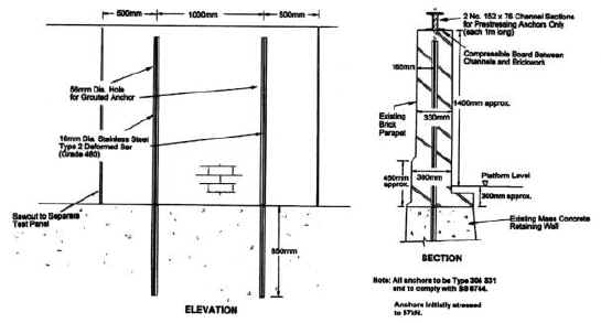
Figure 3 Details of Strengthening Scheme for Test Panel
The vertical Cintec™ anchors were each tensioned up to 57kN and, during jacking, the behaviour of the wall and anchors was monitored, see Figure 4. The elongation of the anchor between the jack and the anchored end in the retaining wall was as expected. However, the wall itself was also found to compress by about 4mm at the top which was significantly greater than the 0.2mm expected. The wall was also found to deflect by about 4mm towards the platform.
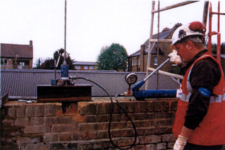
Figure 4 Post-tensioning Anchor in Test Panel
For the supplementary load test, the applied wind load was simulated by the application of a lateral point load on a hothontal spreader beam positioned vertically at the centroid of the wind pressure. The lateral load was applied with a hydraulic jack pushing against a jacking frame anchored to the retaining wall supporting the parapet, see Figure 5.
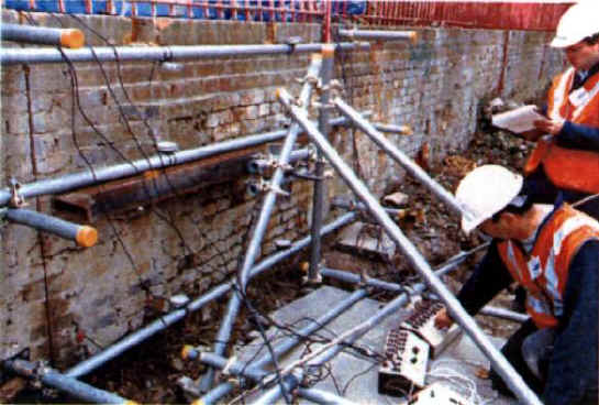
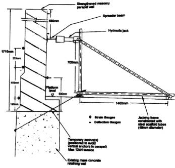
Figure 5 Testing Arrangement
The behaviour of the test panel under lateral loading was monitored using twelve 140mm (5½ inch) strain gauges located on both the tensile and compressive faces and six dial gauges on the tensile face. The test was undertaken with an incremental increase in applied lateral load up to 3.5kN/m, equivalent to 1.6 x nominal wind pressure. The maximum deflection at the top of the wall was 0.38mm while the maximum tensile strain at a position 500mm above the base of the wall was 48 micro strain.
The test results are plotted in Figure 6 against the predicted values which were based on a characteristic masonry strength fk of 2.3N/mm2 and an elastic modulus E of 2.O7kN/mm2 (=0.9fk). The measured results identified that the loading was not uniform across the full panel so, for comparison with predicted values, weighted averages were determined in proportion to the tested area. The measured results demonstrate linear behaviour but give greater strains and deflections than those predicted. This suggests that the masonry strength and/or stiffness assumed for the strengthening calculations were too high. Nevertheless, considering the possible variation of material parameters for old masonry walls, the measured results match the predicted very well.
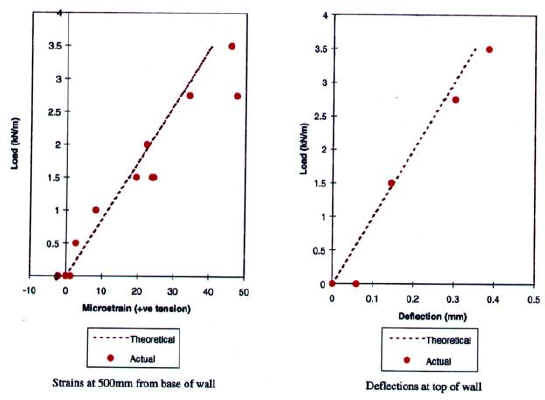
Figure 6 Comparison of Test Results against Predicted
At the end of the test there was no evidence that the loading had caused any damage such as cracking or spalling.
Conclusions
The 2m long test panel of 100 year old parapet wall was post-tensioned against wind and dynamic pressure and suction loading, using two Cintec™ anchors. The supplementary load test with an applied load up to 3.6kN/m (1.6 x nominal loads) demonstrated a linear elastic response.
The predicted response of the strengthened wall, calculated beforehand and based on assumed values for the material properties, were within 30% of the measured values. Bearing in mind the wide range of uncertainties in relation to the wall stiffness and strength, this is surprisingly close. On completion of the test there was no damage such as cracking or spalling.
It is concluded that the supplementary load test was successful in demonstrating the efficacy of strengthening an old brick wall in a poor state of repair. The strengthening scheme presented is an economic and aesthetic solution to the refurbishment of understrength and unstable masonry walls and parapets.
Acknowledgements
The authors would like to thank Dr S Mehrkar-Asl for his assistance during the supplementary load tests and analysis of the results.
References
- ICE National Steering Committee for the Load Testing of Bridges ‘Supplementary Load Testing of Bridges’. Thomas Telford 1998.
Commercial-in-Confidence
Report No. B2056A/R01
May 1999